Understanding the Car Battery Charging Circuit
Key Components:
- Electrical Transformer (T1):
- T1 functions as a voltage step-down device.
- It reduces the grid voltage (typically 120V AC or 240V AC) to a safe level (around 12 volts AC).
- The transformed AC voltage is then fed into the rectifier.
- Rectifier (P1):
- The rectifier is crucial for converting alternating current (AC) from the step-down transformer into direct current (DC).
- Diodes (D1 and D2) within the rectifier bridge ensure unidirectional current flow.
- The rectified DC output becomes suitable for charging the battery.
- Capacitive Filter (C1):
- After rectification, the DC output contains ripples (pulsations) due to the inherent nature of the rectification process.
- C1 acts as a smoothing filter, minimizing these ripples and providing a stable DC output.
- Current-Limiting Protection:
- A series-connected light bulb serves as a current limiter.
- When the battery voltage exceeds 14.4 volts (indicating a fully charged state), the bulb restricts the current flow.
- This prevents overcharging and protects the battery.
Circuit Diagrams:
Circuit diagram of a single-phase transformer with two phase bridge rectifier and capacitive filter:
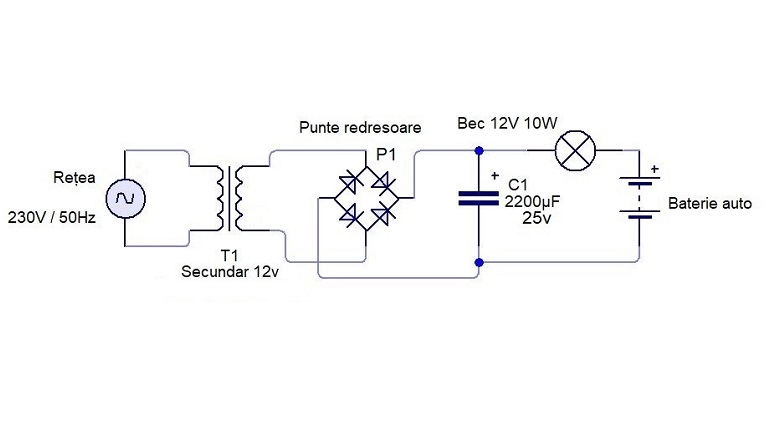
In this design, a center-tapped transformer provides two AC phases, enhancing charging efficiency.
Circuit diagram of a center-tapped full-wave rectifier and capacitive filter:
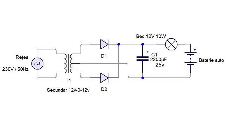
These circuits were drawn in Circuit Wizard 2.00 Student Edition.
Safety Considerations:
Always prioritize safety when working with car batteries and chargers.
Regular maintenance and proper charging techniques can significantly extend battery life.